Earing Defect In Deep Drawing
- Original Article
- Open Access
- Published:
Prediction of Eight Earings in Deep Drawing of 5754O Aluminum Alloy Sheet
Chinese Journal of Mechanical Engineering volume 32, Article number:76 (2019) Cite this article
Abstract
Earings appear easily during deep drawing of cylindrical parts owing to the anisotropic properties of materials. However, current methods cannot fully utilize the mechanical properties of material, and the number of earings obtained differ with the simulation methods. In order to predict the eight-earing problem in the cylindrical deep drawing of 5754O aluminum alloy sheet, a new method of combining the yield stress and anisotropy index (r-value) to solve the parameters of the Hill48 yield function is proposed. The general formula for the yield stress and r-value in any direction is presented. Taking a 5754O aluminum alloy sheet as an example in this study, the deformation area in deep drawing is divided into several equal sectorial regions based on the anisotropy. The parameters of the Hill48 yield function are solved based on the yield stress and r-value simultaneously for the corresponding deformation area. Finite element simulations of deep drawing based on new and existing methods are carried out for comparison with experimental results. This study provides a convenient and reliable way to predict the formation of eight earings in the deep drawing process, which is expected to be useful in industrial applications. The results of this study lay the foundation for the optimization of the cylindrical deep drawing process, including the optimization of the blank shape to eliminate earing defects on the final product, which is of great importance in the actual production process.
Introduction
The Von Mises yield function is the most widely used isotropic yield function for its simple mathematical expression. It is convenient for use in theoretical derivation and finite element (FE) calculation. However, based on the isotropic hypothesis, the Von Mises yield function cannot describe anisotropic materials, especially for sheet metal. After several repetitions of rolling and heat treatment, sheet metals, which have a texture formed by the fibrous structure and preferred orientation of crystallization, exhibit obvious anisotropy [1,2,3,4].
Various anisotropic yield functions have been proposed to describe the anisotropic deformation behavior of materials. Among them, the quadratic anisotropic yield function (Hill48 yield function) proposed by Hill [5] is the most famous and is widely used because of its simple mathematical expression [6,7,8,9,10,11,12]. However, the Hill48 quadratic yield function can only explain four test results, and the results of the "abnormal" yield behavior observed in some processes involving rolled sheet metals cannot be reasonably described. Hence, this model is not always sufficient to represent real physical processes if we use the traditional method to obtain the parameters. Using a different parameter solving method may, however, have a different effect on the accuracy of the yield criteria [1, 13,14,15].
Besides Hill's quadratic yield model, many other anisotropic yield models have been developed. For example, the famous plane stress yield function, Yld2000-2d, was proposed by Barlat et al. [16] to describe the anisotropic plastic deformation of sheet metals, especially for aluminum alloy. The Yld2000-2d yield function involves eight parameters which can be determined by the yield stresses and r-values along 0°, 45°, and 90°, and the equi-biaxial tension direction [16,17,18,19,20]. However, the solid element, which is necessary for some thick sheet metals especially when the stress along normal direction in the sheet plane cannot be ignored, in FE simulation cannot be used with the Yld2000-2d yield function because only plane stress variants are considered. The Yld2004 yield function with 18 parameters proposed by Barlat et al. [21], can predict six or eight earings [22,23,24,25,26,27]. Vegter et al. [28] proposed an anisotropic plane stress yield function based on a yield locus description that applies second order Bezier interpolations. Vegter's yield function requires 17 independent parameters, which is expected to predict six or eight earings [28, 29]. Although some of the above yield functions can take into account more experimental results and predict complex anisotropic behavior, the mathematical expression or the solutions of the parameters are quite complicated, which is inconvenient for engineering application. Besides, a user subroutine is needed to implement the needed yield function into the FE (FE) software, which will increase the cost of FE simulation and cause slow convergence or non-convergence. As mentioned above, Hill's quadratic yield function is the simplest of all the anisotropic yield functions. It involves only four parameters, making it convenient for use in the study. For an isotropic material, the function reduces to the Von Mises yield function. Hence, many researchers still prefer to use Hill's yield model to develop new theories [30,31,32,33,34,35].
The parameters of the Hill48 yield function can be solved using the yield stress or r-value under different loading conditions [1, 14]. Existing studies have shown that both the yield stress and r-value have some effect on the earing phenomenon in deep drawing. However, the number and shape of the earing defects in deep drawing cannot be described accurately by the Hill48 yield function if the parameters are solved with yield stresses or r-values alone [1, 33].
In this study, a new method that takes the yield stress and r-value together into consideration to obtain the parameters of the Hill48 yield function is proposed. The anisotropic behavior of the 5754O aluminum alloy sheet is discussed and FE simulations of the deep drawing test are performed based on different yield functions to predict the earing phenomenon. The proposed method that uses the Hill48 yield function to predict the formation of eight earings in the deep drawing of 575O aluminum alloy sheet is validated using experimental results. This work forms the prerequisite for the deep drawing process optimization including blank shape optimization. It also lays the foundation for the accurate engineering analysis of the anisotropic sheet-forming problem and the realization of an effective FE analysis.
Hill48 Yield Function (Using the Associated Flow Rule)
The expression of the Hill48 yield function is shown in Eq. (1):
$$ \begin{gathered} f = F\left( {\sigma _{{yy}} - \sigma _{{xx}} } \right)^{2} + G\left( {\sigma _{{zz}} - \sigma _{{xx}} } \right)^{2} + H\left( {\sigma _{{xx}} - \sigma _{{yy}} } \right)^{2} \hfill \\ \quad \quad + 2L\sigma _{{yz}}^{2} + 2M\sigma _{{zx}}^{2} + 2\sigma _{{xy}}^{2} = \bar{\sigma }^{2} , \hfill \\ \end{gathered} $$
(1)
where x, y, z represent the orthotropic anisotropic direction. F, G, H, L, M, and N are independent anisotropic characteristic parameters determined from different material tests. \( \bar{\sigma } \) is the equivalent stress. When 3F = 3G = 3H =L =M =N, Eq. (1) will transform the Von Mises yield function for describing an isotropic material. Eq. (1) is appropriate for the FE simulation of sheet metal forming where a solid element should be used so that the stress along the normal direction of sheet is not ignored.
The metal sheet is often in a plane stress state during the forming process, that is, \( \sigma_{zz} \), \( \sigma_{xz} \), \( \sigma_{yz} \) is 0 and then, Eq. (1) can be simplified to
$$ f = \left( {G + H} \right)\sigma_{xx}^{2} - 2H\sigma_{xx} \sigma_{yy} + \left( {H + F} \right)\sigma_{yy}^{2} + 2N\sigma_{xy}^{2} = \bar{\sigma }^{2} . $$
(2)
Eq. (2) is appropriate for the FE simulation with shell- type elements in which only the plane stress is considered, but is not appropriate for that with solid elements where the stress along the normal direction should be considered.
Determination of the Parameters of Hill48 Yield Function
General Formula for Yield Stress and Anisotropy along Different Directions
According to the expression of the Hill48 yield function (Eq. (2)) in the plane stress state, the x and y directions are assumed to be the rolling direction and the transverse direction. The rolling direction is taken as the reference direction, that is, the yield stress in the rolling direction \( \sigma_{0} \) is taken as the reference stress. Therefore, we have
$$ \sigma_{xx} = \sigma_{0} = \bar{\sigma }. $$
(3)
According to the stress transformation formula, the stresses are expressed as:
$$ \left\{ {\begin{array}{*{20}l} {\sigma _{x} = \sigma _{1} \cos ^{2} \alpha + \sigma _{2} \sin ^{2} \alpha - 2\tau _{{xy}} \cos \alpha \sin \alpha ,} \\ {\sigma _{y} = \sigma _{1} \sin ^{2} \alpha + \sigma _{2} \cos ^{2} \alpha + 2\tau _{{xy}} \cos \alpha \sin \alpha ,} \\ {\sigma _{{xy}} = \left( {\sigma _{1} - \sigma _{2} } \right)\cos \alpha \sin \alpha + \tau _{{xy}} \left( {\cos ^{2} \alpha - \sin ^{2} \alpha } \right),} \\ \end{array} } \right.$$
(4)
where \( \sigma_{1} \) is the stress along the angle α with respect to the reference direction, \( \sigma_{2} \) is the stress perpendicular to \( \sigma_{1} \) direction, and \( \tau_{xy} \) is the shear stress along the direction having the angle α. These stresses and the corresponding directions are shown in Figure 1.
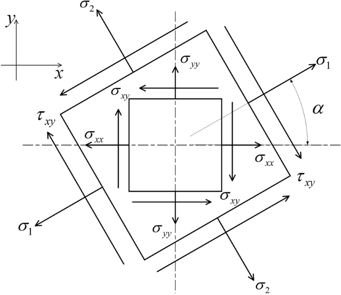
Stresses and corresponding directions at the angle α of the rolling direction
Full size image
The uniaxial tensile stress at an angle α to the rolling direction is set as \( \sigma_{\alpha } \) and then, we have \( \sigma_{1} = \sigma_{\alpha } \), \( \sigma_{2} = 0 \), \( \tau_{xy} = 0 \). Consequently, from Eq. (4), the stress component in the xoy plane is [36].
$$ \left\{ \begin{array}{l} \sigma_{xx} = \sigma_{\alpha } \cos^{2} \alpha , \hfill \\ \sigma_{yy} = \sigma_{\alpha } \sin^{2} \alpha , \hfill \\ \sigma_{xy} = \sigma_{\alpha } \sin \alpha \cos \alpha . \hfill \\ \end{array} \right. $$
(5)
The uniaxial tensile yield stress at the angle α to the rolling direction can be derived based on Eqs. (2), (3), and (5):
$$ \left\{ \begin{array}{l} \sigma_{\alpha } { = }\frac{{\sigma_{0} }}{{\sqrt {A + B + C} }}, \hfill \\ A = \left( {G + H} \right)\cos^{4} \alpha , \hfill \\ B = \left( {F + H} \right)\sin^{4} \alpha , \hfill \\ C = 2\left( {N - H} \right)\sin^{2} \alpha \cos^{2} \alpha . \hfill \\ \end{array} \right. $$
(6)
According to the associated flow criterion, the yield function in Eq. (2) is also a plastic potential function. The plastic strain increments \( {\text{d}}\varepsilon_{x} \), \( {\text{d}}\varepsilon_{y} \), and \( {\text{d}}\gamma_{xy} \) based on the Hill48 yield function can be obtained according to Drucker's formula [37]:
$$ \left\{ \begin{array}{l} {\text{d}}\varepsilon_{xx} = {\text{d}}\lambda \left[ {2\left( {G + H} \right)\sigma_{xx} - 2H\sigma_{yy} } \right], \hfill \\ {\text{d}}\varepsilon_{yy} = {\text{d}}\lambda \left[ {2\left( {F + H} \right)\sigma_{yy} - 2H\sigma_{xx} } \right], \hfill \\ {\text{d}}\gamma_{xy} = 4{\text{d}}\lambda N\sigma_{xy} . \hfill \\ \end{array} \right. $$
(7)
Then, with Eqs. (5) and (7) we have
$$ \left\{ \begin{array}{l} {\text{d}}\varepsilon_{xx} = {\text{d}}\lambda \left[ {2\left( {G + H} \right)\sigma_{\alpha } \cos^{2} \alpha - 2H\sigma_{\alpha } \sin^{2} \alpha } \right], \hfill \\ {\text{d}}\varepsilon_{yy} = {\text{d}}\lambda \left[ {2\left( {F + H} \right)\sigma_{\alpha } \sin^{2} \alpha - 2H\sigma_{\alpha } \cos^{2} \alpha } \right], \hfill \\ {\text{d}}\gamma_{xy} = 4{\text{d}}\lambda N\sigma_{\alpha } \sin \alpha \cos \alpha . \hfill \\ \end{array} \right. $$
(8)
According to the Mohr circle rule for strains, we have,
$$ \varepsilon_{\alpha } { = }\frac{{\varepsilon_{x} + \varepsilon_{y} }}{2} + \frac{{\varepsilon_{x} - \varepsilon_{y} }}{2}\cos 2\alpha + \frac{{\gamma_{xy} }}{2}\sin 2\alpha . $$
(9)
Then, the strain increments \( {\text{d}}\varepsilon_{\alpha } \) in the loading direction and \( {\text{d}}\varepsilon_{\alpha + 90^\circ } \) in the width direction [33] are
$$ \left\{ \begin{array}{l} {\text{d}}\varepsilon_{\alpha } = {\text{d}}\varepsilon_{xx} \cos^{2} \alpha + {\text{d}}\varepsilon_{yy} \sin^{2} \alpha + {\text{d}}\gamma_{xy} \sin \alpha \cos \alpha , \hfill \\ {\text{d}}\varepsilon_{\alpha + 90^\circ } = {\text{d}}\varepsilon_{xx} \sin^{2} \alpha + {\text{d}}\varepsilon_{yy} \cos^{2} \alpha - {\text{d}}\gamma_{xy} \sin \alpha \cos \alpha . \hfill \\ \end{array} \right. $$
(10)
Based on the assumption that the plastic volume is constant, we have
$$ {\text{d}}\varepsilon_{x} + {\text{d}}\varepsilon_{y} + {\text{d}}\varepsilon_{z} = 0 , $$
(11)
$$ {\text{d}}\varepsilon_{z} = - \left( {{\text{d}}\varepsilon_{x} + {\text{d}}\varepsilon_{y} } \right){ = } - 2\left( {G\cos^{2} \alpha + F\sin^{2} \alpha } \right)\sigma_{\alpha } {\text{d}}\lambda . $$
(12)
According to the definition of anisotropy index, the anisotropy index under uniaxial tension along the angle α can be obtained
$$ r_{\alpha } = \frac{{{\text{d}}\varepsilon_{\alpha + 90^\circ } }}{{{\text{d}}\varepsilon_{z} }} = \frac{{H + \left( {2N - F - G - 4H} \right)\sin^{2} \alpha \cos^{2} \alpha }}{{F\sin^{2} \alpha + G\cos^{2} \alpha }}. $$
(13)
Solution of Regional Parameters
The uniaxial tensile yield stresses of 0°, 22.5°, 45°, 67.5°, and 90° direction are set as \( \sigma_{0} \), \( \sigma_{22.5} \), \( \sigma_{45} \), \( \sigma_{67.5} \), and \( \sigma_{90} \), and the anisotropy indexes (r-values) are set as r 0, r 22.5, r 45, r 67.5, and r 90, respectively. The divisions on the sheet metal are shown in Figure 2, where X is the 0° direction (rolling direction), and Y is the 90° direction (transverse direction).
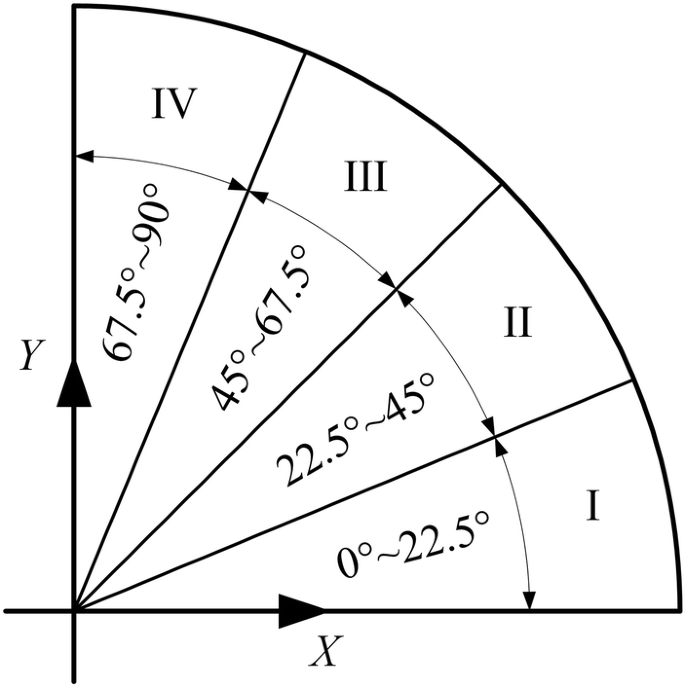
Partitioning of the circular blank sheet (only one quarter of the divided model is displayed, and the four parts are marked I, II, III, and IV)
Full size image
Because of the anisotropy of the materials, the materials properties will vary from the loading directions. In addition, both stress anisotropy and deformation anisotropy play an important role in describing the anisotropic deformation behavior [1]. However, only one class of anisotropy from these can be incorporated in the Hill48 yield function when the parameters are determined using the traditional method. Based on the partitions shown above, more material data will be considered and the simulation results are expected to be more accurate. For example, the boundary of the first region extends from 0° to 22.5°. Both the stresses and r-values along the 0° and 22.5° directions (\( \sigma_{0} \), \( \sigma_{22.5} \), r 0, r 22.5) will be adopted to determine the parameters of the Hill48 yield function. The material properties along the 22.5° direction will be adopted to solve the parameters of the Hill48 yield function for both Parts I and II.
Yield Stress and Anisotropy Index Along Different Directions
In Sect. 3.1, the relationship between the uniaxial material properties (\( \sigma \) and r-value) and the loading direction (α) are obtained.
That is, the yield stress \( \sigma \) and r-value along any direction can be calculated. Then, let α be equal to 0°, 22.5°, 45°, 67.5°, and 90°, respectively. The relation between the parameters of the Hill48 yield function and the uniaxial material properties (yield stresses and r-values) can be obtained as follows.
(1) When α = 0°,
$$ r_{0} = \frac{H}{G}. $$
(15)
(2) When α = 22.5°,
$$ \left( {3 - 2\sqrt 2 } \right)F + \left( {3 + 2\sqrt 2 } \right)G + 4H + 2N = \frac{{8\sigma_{0}^{2} }}{{\sigma_{22.5}^{2} }} , $$
(16)
$$ r_{22.5} = - \frac{F + G - 4H - 2N}{{\left( {4 - 2\sqrt 2 } \right)F + \left( {4 + 2\sqrt 2 } \right)G}}. $$
(17)
(3) When α = 45°,
$$ F + G + 2N = \frac{{4\sigma_{0}^{2} }}{{\sigma_{45}^{2} }} , $$
(18)
$$ r_{45} = - \frac{F + G - 2N}{{2\left( {F + G} \right)}}. $$
(19)
(4) When α = 67.5°,
$$ \left( {3 + 2\sqrt 2 } \right)F + \left( {3 - 2\sqrt 2 } \right)G + 4H + 2N = \frac{{8\sigma_{0}^{2} }}{{\sigma_{67.5}^{2} }} , $$
(20)
$$ r_{67.5} = - \frac{F + G - 4H - 2N}{{\left( {4 + 2\sqrt 2 } \right)F + \left( {4 - 2\sqrt 2 } \right)G}}. $$
(21)
(5) When α = 90°,
$$ F + H = \frac{{\sigma_{0}^{2} }}{{\sigma_{90}^{2} }} , $$
(22)
$$ r_{90} = \frac{H}{F}. $$
(23)
Calculation of the Parameters of Hill48 Yield Function for Each Region
(1) Part I (0°‒22.5°)
For part I, the tensile properties (both yield stresses and r-values) along 0° and 22.5° directions are adopted since the direction of tensile deformation in part I is between 0° and 22.5°. According to Eqs. (14)‒(17),
$$ F = \frac{{\left( {4 + 2\sqrt 2 } \right)\sigma_{0}^{2} }}{{\left( {r_{22.5} + 1} \right)\sigma_{22.5}^{2} }} - \frac{3 + 2\sqrt 2 }{{r_{0} + 1}} , $$
(24)
$$ G = \frac{1}{{r_{0} + 1}} , $$
(25)
$$ H = \frac{{r_{0} }}{{r_{0} + 1}} , $$
(26)
$$ N = \frac{{\left( {4r_{22.5} + 2 + \sqrt 2 } \right)\sigma_{0}^{2} }}{{\left( {r_{22.5} + 1} \right)\sigma_{22.5}^{2} }} - \frac{{2r_{0} + \sqrt 2 + 1}}{{r_{0} + 1}}. $$
(27)
(2) Part II (22.5°‒45°)
Similarly, according to Eqs. (16)‒(19),
$$ F = \frac{{\left( {\sqrt 2 + 1} \right)\sigma_{0}^{2} }}{{\left( {r_{45} + 1} \right)\sigma_{45}^{2} }} + \frac{{\sqrt 2 \sigma_{0}^{2} }}{{\left( {r_{22.5} + 1} \right)\sigma_{22.5}^{2} }} , $$
(28)
$$ G = \frac{{\left( {\sqrt 2 + 1} \right)\sigma_{0}^{2} }}{{\left( {r_{45} + 1} \right)\sigma_{45}^{2} }} + \frac{{\sqrt 2 \sigma_{0}^{2} }}{{\left( {r_{22.5} + 1} \right)\sigma_{22.5}^{2} }} , $$
(29)
$$ H = \frac{{2r_{22.5} \sigma_{0}^{2} }}{{\left( {r_{22.5} + 1} \right)\sigma_{22.5}^{2} }} - \frac{{\left( {2r_{45} + 1} \right)\sigma_{0}^{2} }}{{\left( {r_{45} + 1} \right)\sigma_{45}^{2} }} , $$
(30)
$$ N = \frac{{\left( {2r_{45} + 1} \right)\sigma_{0}^{2} }}{{\left( {r_{45} + 1} \right)\sigma_{45}^{2} }} . $$
(31)
(3) Part III (45°‒67.5°)
From Eqs. (18)‒(21),
$$ F = \frac{{\left( {1 - \sqrt 2 } \right)\sigma_{0}^{2} }}{{\left( {r_{45} + 1} \right)\sigma_{45}^{2} }} + \frac{{\sqrt 2 \sigma_{0}^{2} }}{{\left( {r_{67.5} + 1} \right)\sigma_{67.5}^{2} }} , $$
(32)
$$ G = \frac{{\left( {\sqrt 2 + 1} \right)\sigma_{0}^{2} }}{{\left( {r_{45} + 1} \right)\sigma_{45}^{2} }} - \frac{{\sqrt 2 \sigma_{0}^{2} }}{{\left( {r_{67.5} + 1} \right)\sigma_{67.5}^{2} }} , $$
(33)
$$ H = \frac{{2r_{67.5} \sigma_{0}^{2} }}{{\left( {r_{67.5} + 1} \right)\sigma_{67.5}^{2} }} - \frac{{\left( {2r_{45} + 1} \right)\sigma_{0}^{2} }}{{\left( {r_{45} + 1} \right)\sigma_{45}^{2} }} , $$
(34)
$$ N = \frac{{\left( {2r_{45} + 1} \right)\sigma_{0}^{2} }}{{\left( {r_{45} + 1} \right)\sigma_{45}^{2} }} . $$
(35)
(4) Part IV (67.5°‒90°)
From Eqs. (20)‒(23),
$$ F = \frac{{\sigma_{0}^{2} }}{{\left( {r_{90} + 1} \right)\sigma_{90}^{2} }} , $$
(36)
$$ G = \frac{{\left( {4 + 2\sqrt 2 } \right)\sigma_{0}^{2} }}{{\left( {r_{67.5} + 1} \right)\sigma_{67.5}^{2} }} - \frac{{\left( {3 + 2\sqrt 2 } \right)\sigma_{0}^{2} }}{{\left( {r_{90} + 1} \right)\sigma_{90}^{2} }} , $$
(37)
$$ H = \frac{{r_{90} \sigma_{0}^{2} }}{{\left( {r_{90} + 1} \right)\sigma_{90}^{2} }} , $$
(38)
$$ N = \frac{{\left( {4r_{67.5} + 2 + \sqrt 2 } \right)\sigma_{0}^{2} }}{{\left( {r_{67.5} + 1} \right)\sigma_{67.5}^{2} }} - \frac{{\left( {2r_{90} + 1 + \sqrt 2 } \right)\sigma_{0}^{2} }}{{\left( {r_{90} + 1} \right)\sigma_{90}^{2} }} . $$
(39)
Performance of Different Yield Functions in Predicting Earing
Solution for Stress and Strain
The 5754O aluminum alloy sheet was used as sample for the uniaxial tensile test. The material constants of the sheet are shown in Table 1 [38].
Full size table
The stress-strain values are calculated using the Voce-shaped stress-strain relationship. The expression is given by [38]
$$ \bar{\sigma } = \sigma_{0} + q\left( {1 - \exp \left( { - b\bar{\varepsilon }_{\text{p}} } \right)} \right) , $$
(40)
where \( \bar{\sigma } \) is the equivalent stress, \( \sigma_{0} \) is the initial yield strength, \( \bar{\varepsilon }_{\text{p}} \) is the equivalent plastic strain, q and b are the fitted material constants; the parameter values are shown in Table 2 [1].
Full size table
Solution for Anisotropic Parameters
The anisotropy parameters of the Hill48 yield function are obtained using Eqs. (24)‒(39) and the values in Table 1 and Table 2, and the region-specific parameters are shown in Table 3.
Full size table
In Abaqus, anisotropic yield behavior is defined based on the Hill48 yield function and six specific parameters are required to characterize the anisotropic properties of materials. However, only four specific parameters need to be calculated under the plane stress state.
The four coefficients of the Hill48 yield function under the plane stress state are defined as Eq. (41) [14]:
$$ \left\{ \begin{array}{l} F = \frac{1}{{2R_{22}^{2} }} + \frac{1}{{2R_{33}^{2} }} - \frac{1}{{2R_{11}^{2} }}, \\ G = \frac{1}{{2R_{11}^{2} }} + \frac{1}{{2R_{33}^{2} }} - \frac{1}{{2R_{22}^{2} }}, \\ H = \frac{1}{{2R_{11}^{2} }} + \frac{1}{{2R_{22}^{2} }} - \frac{1}{{2R_{33}^{2} }}, \\ N = \frac{3}{{2R_{12}^{2} }}. \\ \end{array} \right. $$
(41)
where \( R_{11} \), \( R_{22} \), \( R_{33} \) and \( R_{12} \) are four specified material parameters for using the Hill48 yield function in Abaqus. There are two other parameters, \( R_{13} \) and \( R_{23} \), whose values are assumed as \( R_{13} = R_{23} { = }1 \). Then, according to Eq. (41), \( R_{ij} \) can be written as Eq. (42). The calculation results are shown in Table 4.
Full size table
$$ \left\{ \begin{array}{l} R_{11} = \sqrt {\frac{1}{G + H}} , \\ R_{22} = \sqrt {\frac{1}{F + H}} , \\ R_{33} = \sqrt {\frac{1}{F + G}} , \\ R_{12} = \sqrt {\frac{3}{2N}} . \\ \end{array} \right. $$
(42)
FE Simulation of Deep Drawing Test
Based on the above data, the FE simulation of the 5754O aluminum alloy sheet is performed. A deep drawing test was carried out on the sheet metal test machine. The process parameters are shown in Table 5. The schematic diagram of the deep drawing test is shown in Figure 3 [1].
Full size table
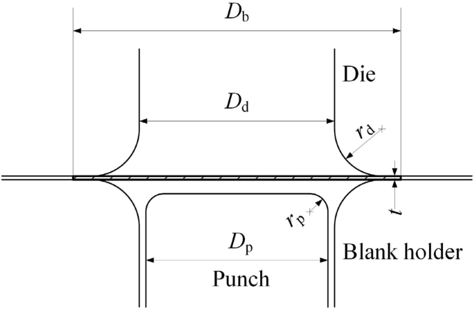
Schematic diagram of deep drawing
Full size image
We take four nodes located in different locations from the edge to the center along the radial direction, followed by the node 1, the node 2, the node 3, and the node 4, as is shown in Figure 4. Figure 5 shows the strain-time curves of the four nodes. It can be seen from Figure 5 that strain of four points does not increase until a certain time. The closer to center the point is, the smaller the plastic deformation is, and the quicker the strain is to reach the maximum value. The greater the plastic deformation at the point near the edge, the later the strain reaches its maximum value. When the blank enters the cup wall, the plastic deformation no longer increases obviously. Therefore, we can speculate that the main deformation process of earings is before the material enters the cup wall.
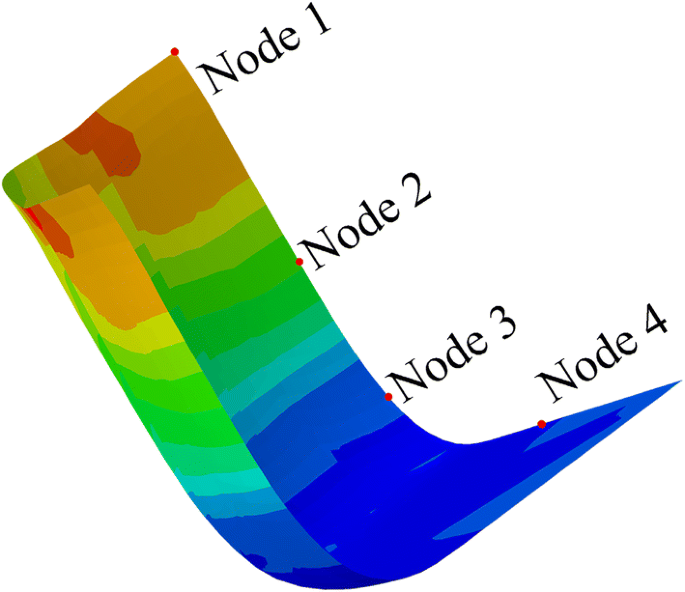
Location of four nodes along the radial direction
Full size image
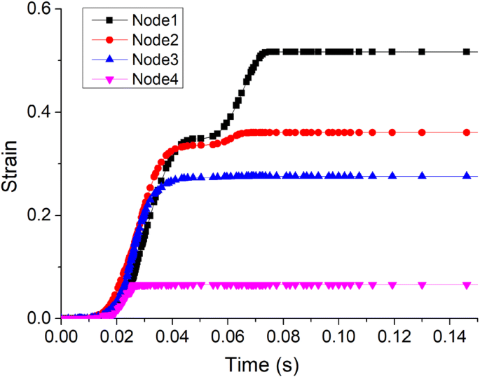
Strain-time curves of nodes from the edge to the center in the radial direction
Full size image
Three yield functions, namely, Yld2000-2d (implemented into ABAQUS by coding UMAT subroutine), Von Mises, and Hill48, are adopted to carry out the deep drawing simulations. The Hill48 parameters are determined using the traditional method and the proposed method shown above. Figure 6(a) shows the final shape of the part as obtained from the simulation based on Hill48 where the parameters are determined by the method proposed in this study. Figure 6(b) shows the experimental results and Figure 6(c) shows the comparison of experimental and simulation results. We compared the simulation results and the experimental results in terms of the part port height as shown in Figure 7. The simulation results based on the Hill48 yield function along with the parameter determination method proposed in this study can almost accurately predict the number and shape of the earings. The simulation results are in good agreement with the experimental results in the range of 0°‒360°.
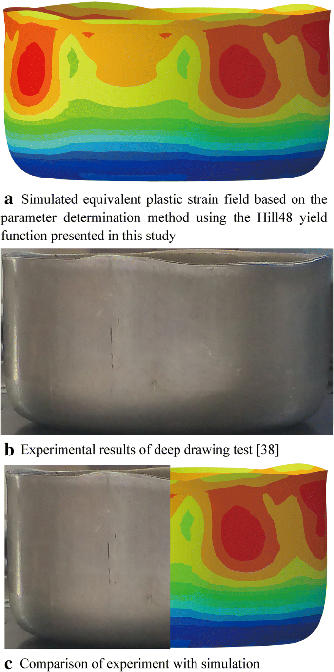
Comparison of the simulation results for each method with the experimental results
Full size image
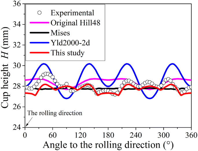
Comparison of simulation results and experimental results based on shell element
Full size image
When conditions other than the method are the same, and the step time is 1 s, it can be seen from Figure 8 that the computation time is the longest for Yld2000, which is much longer than that required for the other three methods. The other three methods have similar computation times, which are shorter. The computation time based on the new method proposed in this paper is slightly less than that based on the original Hill48 yield criterion, which saves time and increases efficiency.
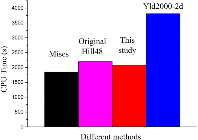
Computation time for different methods
Full size image
Discussions
As shown in Figure 7, we can see that, for the 5754O aluminum alloy sheet, different yield functions have a great influence on the prediction of earing. The Yld2000-2d yield criterion not only involves a large number of parameters and computations, but also can only predict up to four earings. The results obtained based on the original Hill48 yield criterion also cannot accurately describe the earings when compared with experimental result. The proposed new method combined with the FE simulation successfully predicted the eight earings, which can describe the experimental results more accurately. The simulated earing shape and trend are in good agreement with the experimental results. It can be seen from Figure 6(c) and Figure 7 that the results obtained using the new method are in good agreement with the experimental results. The above conclusions are applicable to other sheet metals as well. Shell type elements (S4R) are adopted in the simulated results shown in Figure 6. Similar results can be obtained with solid elements (e.g., C3D8R), which will not be demonstrated in this study.
The two traditional methods of the Hill48 yield function cannot accurately describe the stress anisotropy and the deformation anisotropy in different directions at the same time, while only one method can be used to solve the anisotropic parameters in practical applications [1]. With the method proposed in this study, which takes into account the stress anisotropy and deformation anisotropy simultaneously, the theoretical calculation and the simulation accuracy can be improved. As can be surmised from the general expression for the yield stress and anisotropy index at any angle in Sect. 3.1, the yield stress and anisotropy index in the direction of the boundary in a certain region can be obtained. Then, the anisotropic characteristic parameters are determined and the corresponding simulated results coincide with the experimental results. Besides, this avoids complex calculations when using other specialized yield functions to solve the parameters and does not increase the corresponding FE simulation costs.
Conclusions
- (1)
A brand new method to predict eight earings that may occur during the deep drawing process is proposed. We divide a quarter-circular blank into four equal sectorial regions, and use the yield stress and anisotropy index simultaneously to solve for the parameters in each region.
- (2)
Based on the theories of elastic-plastic mechanics, the Hill48 quadratic yield model is taken as the research object of study for solution, and obtain a general expression for the material property parameters - yield stress and anisotropy index at any angle.
- (3)
Based on the new method, the FEFE simulation of the deep drawing process of a 5754O aluminum alloy sheet are carried out, and eight earings are successfully predicted, which is in good agreement with the experimental results.
- (4)
In practical applications, the new method of solving parameters takes into account the stress anisotropy and deformation anisotropy at the same time, which provides a new method for solving for the parameters, thus making the Hill48 yield function convenient to use. This method will lay the foundation for blank shape optimization procedures in the future. It is also expected to be helpful in accurate engineering analysis and effective FE analysis of anisotropic sheet metal forming problems.
References
- [1]
H B Wang, M Wan, Y Yan, et al. Effect of the solving method of parameters on the description ability of the yield criterion about the anisotropic behavior. Journal of Mechanical Engineering, 2013, 49(24): 45-53. (in Chinese)
Article Google Scholar
- [2]
Y Sun, C Z Chi, L C Li, et al. Effect of anisotropic of ZK60 magnesium alloy sheet on its earing behavior during deep drawing process. Journal of Plasticity Engineering, 2017, 24(1): 85-91.(in Chinese)
Google Scholar
- [3]
H B Wang, M L Men, Y Yan, et al. Accurate analysis of anisotropic deformation behavior of 5754O aluminum alloy sheet under proportional/non-proportional loading Paths. Journal of Mechanical Engineering, 2018, 54(24): 77-87 .(in Chinese)
Article Google Scholar
- [4]
M Athale, A K Gupta, S K Singh, et al. Analytical and finite element simulation studies on earing profile of Ti-6Al-4V deep drawn cups at elevated temperatures. International Journal of Material Forming, 2017(2013): 1-12.
Google Scholar
- [5]
R A Hill. A theory of the yielding and plastic flow of anisotropic metals. Proceedings of the Royal Society A, 1948, 193(1033): 281-297.
MathSciNet Article Google Scholar
- [6]
B T Tang, Y S Lou. Effect of anisotropic yield functions on the accuracy of material flow and its experimental verification. Acta Mechanica Solida Sinica, 2019, 32(1): 50-68.
Article Google Scholar
- [7]
A Taherizadeh, D E Green, J W Yoon. Evaluation of advanced anisotropic models with mixed hardening for general associated and non-associated flow metal plasticity. International Journal of Plasticity, 2011, 27(11): 1781-1802.
Article Google Scholar
- [8]
S Bagherzadeh, M J Mirnia, B Mollaei Dariani. Numerical and experimental investigations of hydro-mechanical deep drawing process of laminated aluminum/steel sheets. Journal of Manufacturing Processes, 2015, 18: 131-140.
Article Google Scholar
- [9]
W L Hu. A novel quadratic yield model to describe the feature of multi-yield-surface of rolled sheet metals. International Journal of Plasticity, 2007, 23(12): 2004-2028.
Article Google Scholar
- [10]
S M Hussaini, G Krishna, A K Gupta, et al. Development of experimental and theoretical forming limit diagrams for warm forming of austenitic stainless steel 316. Journal of Manufacturing Processes, 2015, 18: 151-158.
Article Google Scholar
- [11]
K E N'souglo, J A Rodríguez-Martínez, A Vaz-Romero, et al. The combined effect of plastic orthotropy and tension-compression asymmetry on the development of necking instabilities in flat tensile specimens subjected to dynamic loading. International Journal of Solids and Structures, 2019, 159: 272-288.
Article Google Scholar
- [12]
C W Hu, S H Cui, W Y Li, et al. Experiment study on drawing earing of cylindrical cups by variable gap deep drawing. Journal of Plasticity Engineering, 2016, 23(2): 75-80.
Google Scholar
- [13]
H B Wang, Y Yan, M Wan, et al. Experimental investigation and constitutive modeling for the hardening behavior of 5754O aluminum alloy sheet under two-stage loading. International Journal of Solids and Structures, 2012, 49(26): 3693-3710.
Article Google Scholar
- [14]
Y Yan, H B Wang, Q Li. The inverse parameter identification of Hill 48 yield criterion and its verification in press bending and roll forming process simulations. Journal of Manufacturing Processes, 2015, 20: S1526612515001061.
Article Google Scholar
- [15]
D M Neto, M C Oliveira, J L Alves, et al. Influence of the plastic anisotropy modelling in the reverse deep drawing process simulation. Materials & Design, 2014, 60: 368-379.
Article Google Scholar
- [16]
F Barlat, J C Brem, J W Yoon, et al. Plane stress yield function for aluminum alloy sheets—Part 1: Theory. International Journal of Plasticity, 2003, 19(9): 1297-1319.
Article Google Scholar
- [17]
Y Yan, C Wu, Z L Hu, et al. Anisotropic yield criterion for automotive aluminum panels forming numerical simulation. Journal of Plasticity Engineering, 2016, 23(2): 92-97. (in Chinese)
Google Scholar
- [18]
E H Lee, B S Thomas, J W Yoon, A yield criterion through coupling of quadratic and non-quadratic functions for anisotropic hardening with non-associated flow rule. International Journal of Plasticity, 2017, 99(1): 120-143.
Article Google Scholar
- [19]
J W Yoon, F Barlat, R E Dick, et al. Plane stress yield function for aluminum alloy sheets—part II: FE formulation and its implementation. International Journal of Plasticity, 2004, 20(3): 495-522.
Article Google Scholar
- [20]
H B Wang, M Wan, X D Wu, et al. The equivalent plastic strain-dependent Yld2000-2d yield function and the experimental verification. Computational Materials Science, 2009, 47(1): 22.
Article Google Scholar
- [21]
F Barlat, H Aretz, J W Yoon, et al. Linear transfomation-based anisotropic yield functions. International Journal of Plasticity, 2005, 21(5): 1009-1039.
Article Google Scholar
- [22]
J W Yoon, F Barlat, R E Dick, et al. Prediction of six or eight ears in a drawn cup based on a new anisotropic yield function. International Journal of Plasticity, 2006, 22(1): 174-193.
Article Google Scholar
- [23]
J Noder, A Abedini, T Rahmaan, et al. An experimental and numerical investigation of non-isothermal cup drawing of a 7XXX-T76 aluminum alloy sheet. IOP Conference Series Materials Science and Engineering, 2018, 418(1): 012019.
Article Google Scholar
- [24]
H Fukumasu, T Kuwabara, H Takizawa. Influence of material modeling on earing prediction in cup drawing of AA3104 aluminum alloy sheet. Journal of Physics Conference Series, 2016, 734(3): 032022.
Article Google Scholar
- [25]
S Anubhav, B Shamik, P S L Prakash, et al. Prediction of earing defect and deep drawing behavior of commercially pure titanium sheets using CPB06 anisotropy yield theory. Journal of Manufacturing Processes, 2018, 33: 256-267.
Article Google Scholar
- [26]
Y Shi, H Jin, P D Wu. Analysis of cup earing for AA3104-H19 aluminum alloy sheet. European Journal of Mechanics - A/Solids, 2018, 69: 1-11.
Article Google Scholar
- [27]
S J Zhang, Y S Lou, J W Yoon. Earing prediction of AA 2008-T4 with anisotropic Drucker yield function based on the second and third stress invariants. Journal of Physics Conference Series, 2018, 1063(1): 012113.
Google Scholar
- [28]
H Vegter, A H V D Boogaard. A plane stress yield function for anisotropic sheet material by interpolation of biaxial stress states. International Journal of Plasticity, 2005, 22(3): 557-580.
Article Google Scholar
- [29]
H B Wang, Y Yan, M Wan, et al. A quadratic yield function with multi-involved-yield surfaces describing anisotropic behaviors of sheet metals under tension/compression. Acta Mechanica Solida Sinica, 2017, 30(6): 618-629.
Article Google Scholar
- [30]
J H Lian, F H Shen, X X Jia, et al. An evolving non-associated Hill48 plasticity model accounting for anisotropic hardening and r-value evolution and its application to forming limit prediction. International Journal of Solids and Structures, 2017: S0020768317301580.
- [31]
J E Zhu, Y Xia, H L Luo, et al. Influence of flow rule and calibration approach on plasticity characterization of DP780 steel sheets using Hill48 model. International Journal of Mechanical Sciences, 2014, 89(4): 148-157.
Article Google Scholar
- [32]
X Xue, J Liao. Assessment of yield criterion for deformation prediction in cross-die deep drawing of DC05 steel sheet. Journal of Plasticity Engineering, 2018, 25(4): 217-224 .(in Chinese)
Google Scholar
- [33]
H B Wang, Z Y Chen, Y Yan. Capabilities of yield criteria on predicting the anisotropic behaviors of DP600 steel sheet. Journal of Plasticity Engineering, 2015, 22(2): 45-50.(in Chinese)
Google Scholar
- [34]
H B Wang, M Wan, Q Li, et al. Deformation behavior of TRIP590 advanced high strength steel under biaxial loading. Journal of Mechanical Engineering, 2016, 52(6): 46-58. (in Chinese)
Article Google Scholar
- [35]
F Ozturk, S Toros, S Kilic. Effects of anisotropic yield functions on prediction of forming limit diagrams of DP600 advanced high strength steel. Procedia Engineering, 2014, 81: 760-765.
Article Google Scholar
- [36]
H B Wang, W Zhou, Y Yan, et al. Parameter determination method of Gotoh yield criterion based on non-associated flow rule. Chinese Journal of Theoretical and Applied Mechanics, 2018, 50(5): 1051-1062. (in Chinese)
Google Scholar
- [37]
H B Wang, Y Yan, F Han, et al. Experimental and theoretical investigations of the forming limit of 5754O aluminum alloy sheet under different combined loading paths. International Journal of Mechanical Sciences, 2017, 133: 147-166.
Article Google Scholar
- [38]
H B Wang. Yielding and hardening behavior and forming limit for sheet metal under complex loading paths. Beijing: Beihang University, 2009. (in Chinese)
Google Scholar
Download references
Authors' Contributions
HW was in charge of the whole trial; HW and MM wrote the manuscript; YY, MW and QL assisted with sampling and laboratory analyses. All authors read and approved the final manuscript.
Authors' Information
Haibo Wang, born in 1980, is currently a professor at School of Mechanical and Materials Engineering, North China University of Technology, China. He received his doctorate from Beihang University, China, in 2009. His research interests include sheet metal forming theory, numerical simulation and experimental techniques.
Mingliang Men, born in 1995, is currently a master candidate at School of Mechanical and Materials Engineering, North China University of Technology, China.
Yu Yan, born in 1981, is currently an associate professor at School of Mechanical and Materials Engineering, North China University of Technology, China. She received her doctorate from Beihang University, China, in 2010. Her research interests include sheet metal forming process and finite element simulation.
Min Wan, born in 1962, is currently a professor at School of Mechanical Engineering and Automation, Beihang University, China. He received his doctorate from Harbin Institute of Technology, China, in 1995. His research interests include digital forming technology and system, sheet metal forming theory and experimental techniques, new craft and technology of airplane sheet metal.
Qiang Li, born in 1963, is currently a professor at School of Mechanical and Materials Engineering, North China University of Technology, China. He received his doctorate from Huazhong University of Science and Technology, China, in 1998. His research interests include variable section roll forming technology.
Competing Interests
The authors declare that they have no competing interests.
Funding
Supported by National Natural Science Foundation of China (Grant No. 51475003) and Beijing Youth Top Talents Training Program.
Rights and permissions
Open Access This article is distributed under the terms of the Creative Commons Attribution 4.0 International License (http://creativecommons.org/licenses/by/4.0/), which permits unrestricted use, distribution, and reproduction in any medium, provided you give appropriate credit to the original author(s) and the source, provide a link to the Creative Commons license, and indicate if changes were made.
Reprints and Permissions
About this article
Cite this article
Wang, H., Men, M., Yan, Y. et al. Prediction of Eight Earings in Deep Drawing of 5754O Aluminum Alloy Sheet. Chin. J. Mech. Eng. 32, 76 (2019). https://doi.org/10.1186/s10033-019-0390-2
Download citation
-
Received:
-
Revised:
-
Accepted:
-
Published:
-
DOI : https://doi.org/10.1186/s10033-019-0390-2
Keywords
- Anisotropy
- Deep drawing
- Yield function
- Finite element simulation
Earing Defect In Deep Drawing
Source: https://cjme.springeropen.com/articles/10.1186/s10033-019-0390-2
Posted by: pullenmrseach.blogspot.com

0 Response to "Earing Defect In Deep Drawing"
Post a Comment